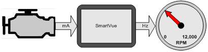
In most processes some level of signal conversion is usually necessary and generally requires additional hardware. When using the SmartVueTM the need for addition signal conversion hardware can be eliminated by assigning unused inputs and outputs for this purpose.

The SmartVueTM is capable of converting virtually all of its signal inputs to outputs of the same or different signal types. The signals can be scaled, inverted, or using thresholds analog inputs can be converted to digital outputs. For added flexibility digital inputs can also be used to control analog outputs, producing two unique fixed analog output levels for both the high and low input states.

In the following examples you will see how to convert inputs to outputs of various types and view live conversion data using the monitor data feature.

Current Loop Input to Frequency Output Conversion

In this example we will convert a current loop signal providing engine RPM to a frequency output to connect to a stand alone RPM gauge.

Current Loop In to Frequency Out

Let’s assume the engine controller outputs 0 to 10,000 RPM using a 4 to 20mA signal and the RPM gauge indicates 0 to 12,000 RPM with a frequency input range of 0 to 5,000Hz.

We will use current loop input #1 and frequency output #2 for the signal conversion using the conversion tables below.

Current Loop Input #1

Signal Value (mA) Scaled Value (RPM)
4 0
20 10,000

Frequency Output #2

Scaled Value (RPM) Signal Value (Hz)
0 0
12,000 5,000

Let’s start by setting the scaling, units, and labels for current loop input #1 and frequency output #2 as shown by the following screens.

Min/Max Value

The “Min Value” and “Max Value” entries are lower and upper scaling points and do not limit the signal range. Setting the “Min Value” to 8mA = 2500 RPM and “Max Value” to 16mA = 7500 RPM would produce the same results.

Now that the current loop input is configured and scaled let’s configure the frequency output.

With the I/O scaling completed it is time to connect a process to the current loop input. Configure “Process 1” by following the screens below.

Each process can be configured with different input scaling, but in this case let’s load the scaling and labels that we entered during the I/O configuration by pressing “Load Settings from IOConfig”.

On select inputs the “Input Filter” menu is available to adjust the sample interval and averaging. In this case let’s use the fastest sample interval of 20ms and no averaging (1 Sample).

Now that we have a process configured to read and scale the current loop input #1 we can connect this process to frequency output #2.

Current loop input #1 is now connected to frequency output #2 with the required scaling.

Yes (auto disable) When an output is enabled with the “auto disable” feature, the output will automatically be disabled if either an input error occurs or an input setting is changed that can affect the outputs value.

To confirm the conversion is working as expected you can use the “Monitor Data” feature to see a live view of the inputs and outputs.

Monitor Data
The monitor data display shows live I/O values using the scaling and labels set in the “Configure I/O” menu.

Controlling Digital Outputs

Analog, counters, and J1939 inputs can be used to toggle digital outputs based on a set of low and high threshold values or latch digital outputs based on a latching threshold.

Using the RPM signal from “Process 1” configured in the previous example, we will configure a digital output to latch at a low level if the engine speed reaches or exceeds 6,000 RPM.

Controlling Digital Outputs with J1939 Input Data
More options are available when controlling a digital output using a J1939 input. Refer to the user manual and application note 50-0005 “J1939 Engine Monitoring” for more information.

First let’s configure multipurpose I/O #1 as a Digital Output and set the low level label to “OVER” and the high impedance (HiZ) label to “OK”. These labels are displayed when viewing the output states from the monitor data screen.

Open Collector Outputs
The digital outputs are open collector and can be pulled up as high as 30V. An internal 10K pull-up can be enabled from the “Configure I/O -DIO/VIN” screen. It is possible to connect multiple open collector outputs together to create logic ‘OR’ functionality.

Now that we have the digital output configured let’s connect it to the RPM process that we had configured in the previous example.

Once the process is selected and the output is enabled navigate to the next screen to set the output mode. Here we select the latching mode and configure the output to latch low when the engine speed is greater than or equal to 6000 RPM.

Now that the output is being controlled we can view the output state using the “Monitor Data” feature.

In the first window above the engine speed has not reached the 6,000 RPM limit so the digital output “RPM TRIP” is in the high impedance state, the second window shows the engine speed exceeded the 6,000 RPM threshold and the digital output is now switched low and in the third window the engine speed has returned to a level below 6000 RPM and the digital output is still low due to the latching functionality.

The output latch condition can be cleared either by entering the “DOUT 1” configuration screen and pressing “OK” or directly from the meter screen by pressing a meter indicator button that is linked to “DOUT 1”. See the SmartVueTM user manual for information on configuring meter indicators.

Digital Input Conversion

With SmartVueTM‘s large digital input signal range and variable input threshold voltage a wide variety of digital input signals can be processed and converted to digital outputs, voltage outputs, current loop outputs or frequency outputs.

In this example let’s control a 4-20mA valve using a 5V logic signal. To make things more interesting let’s use a low logic signal to turn the valve on at 50% (12mA) and a high logic level to turn the valve off (4mA).

Conversion Table
Current Loop Output (mA)
Low 12
High 4

First we can set the digital input threshold value, let’s use 2V which is the default.

Since we have already assigned the first multipurpose I/O in the example above let’s assign the second channel to the valves On/Off control input. Here we set the low state label to “ON” and the high state label to “OFF”.

Next we configure the current loop output scaling and labels. Let’s use current loop output channel #1.

At this point we need to configure a process to read the digital input. Since “Process 1” is in use let’s use “Process 2” and connect it to the multipurpose I/O “DIN 2”.

Now that the process is configured we can connect it to the current loop output assigned to control the valve.

Select the process “P2: Valve” and navigate to the next screen to configure the current loop output levels for each input state. To turn the valve on at 50% when the input is low enter 12mA for the “ON (low)” state and to turn the valve off when the input is high enter 4mA for the “OFF (high)” state.

Now that the digital input is linked to the current loop output navigate to the monitor data screen to view the live I/O data. Here you will see the “4-20mA OUT 1” is 12mA when “DIN 2” is low (ON) and 4mA when “DIN 2” is high (OFF).

Converting Quadrature Encoder/Counters & Tachometer Inputs

The SmartVueTM is capable of using the rate (frequency) or total accumulated from any one of its counter or tachometer inputs to directly control an output.

In this example we will measure the fluid volume within a tank using a quadrature encoder and output a voltage that is proportional to this volume.

Let’s assume in quadrature (x4) mode the encoder outputs 4000 counts per cm of fluid and the tank has a 1 meter radius. Converting to volume the encoder will produce 127.324 counts per liter which will be used as the K factor when setting up the encoder input.

We start by configuring “Counter 3” as shown by the screens below entering the K factor determined above.

Enter the labels and units for both the rate and total and select the desired time base for the rate. In this example we will select a time base of minutes.

Since we are connecting to a quadrate encoder set the mode to “Quad x4”.

Now that the counter is configured let’s setup the voltage output. Assuming the tank holds a maximum of 1000 liters let’s configure the voltage output to produce 0V when empty and 10V when full.

Voltage Outputs
The voltage outputs are isolated and are referenced to the “Isolated 24V-” terminal J1-3.

We will now connect “Process 3” to the quadrature input “QEnc 1”. Note when the mode of “Counter 3” is changed to “Quad x2” or “Quad x4” the counter is renamed to “QEnc 1”.

Now that both the counter input and process have been configured we can attach the process to the voltage output.

Since we are connected to a Total/Rate process we can connect the output to either the processes total or rate data point. We want the voltage output to change based on the volume of fluid in the tank so select the “Total: Volume” data point.

Now that the configuration is complete we can view the tank level voltage output from the monitor data screen. We can see the tank level is at 197.32L and the voltage output is at 1.9732V. We can also see that the tank is filling at a rate of 58.43L/min.

Meter Display

Normally SmartVueTM is configured to display process data directly on the meter screen, but as shown in the examples above it can also process data in the background while saving the meter display area for data of higher importance.

For users not familiar with the meter display capabilities of SmartVueTM a few meter samples are shown below. The data displayed on these meters are generated by the I/O and processes configured in the previous examples. See the SmartVueTM user manual for information on configuring meters.